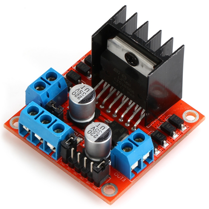

If you remove the jumper, the onboard voltage regulator is disabled and the +5V pin at #6 is no longer active. You can now use the +5V pin at #6 (and the GND pin at #5) to power your Arduino. Connect to PWM output for DC motor speed control.Ĭonnect the L298N stepper driver board to a 9V…12V power supply using pin #4 (+12V) and #5 (GND). Leave this in place when using a stepper motor. Connect to PWM output for DC motor speed control. 5V output if the 12V jumper at #3 is in place.Connect your motor supply voltage here, maximum of 35V DC.When the jumper is in place, the onboard voltage regulator is active (12V max to 5V). 12V jumper – remove this if using a supply voltage greater than 12V DC.They will not have as much torque as bipolar motors due to thinner wire with a higher electrical resistance used in the coils (bifilar windings). Note: You can also connect 5,6 or 8 wire unipolar motors and connect them as bipolar motors by not connecting the common lead(s).
#L298N STEPPER MOTOR DRIVER CONTROLLER BOARD DATASHEET GENERATOR#
Flyback diodes are required to prevent voltage spikes when the power to the coil is turned off and the stepper motor acts like a generator briefly (back-emf). Bipolar motors offer increased torque compared to unipolar motors. Note that the number of poles inside a stepper motor is often greater than just 2 individual physical poles inside the stepper motor are wired in series to create 2 coils / 4 wires you see in schematics.īipolar stepper motors require a dual H-bridge to drive them one H-bridge for each coil. Coil B current flowing ‘right to left’.Coil B current flowing ‘left to right’.Coil A current flowing ‘right to left’.Coil A current flowing ‘left to right’.By driving the current in seperate directions through each of the coils, we can have a total of 4 different states: Bipolar stepper motors always have 2 coils.

Bipolar stepper motors always have only 4 wires.


 0 kommentar(er)
